แสดงกระทู้

This section allows you to view all posts made by this member. Note that you can only see posts made in areas you currently have access to.


Messages - wm5398

หน้า: 1 ... 14 15 [16] 17 18 ... 27
271
Cameron Gate Valve with API6A standard

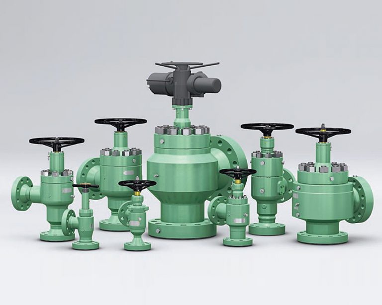
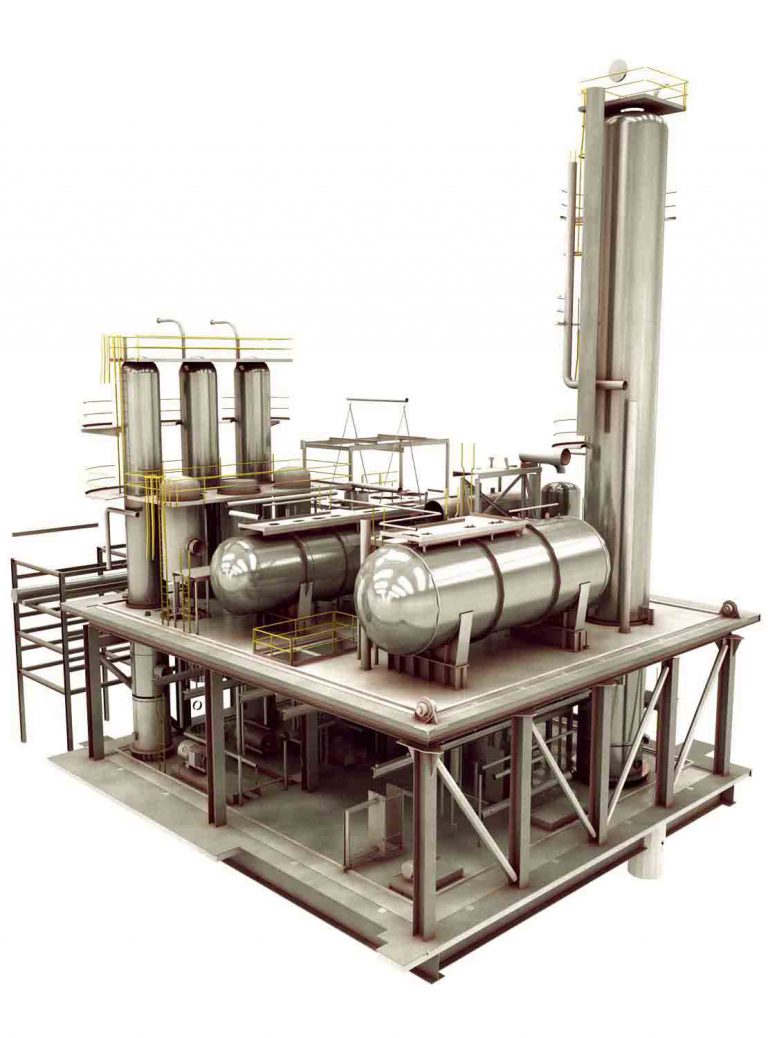
Over the course of the last century, numerous gate valve design genres have been developed for use in the oil and gas industry. Designs that have commonly been used to control fluid through production trees and flowlines include expanding , wedge, and slab-style gate valves. Cameron engineers have selected the best-suited features for development and impletiontation into Cameron Gate Valve with API6A standard

Overview – Cameron Gate Valve with API6A standard
        - Cameron designs and manufactures gate valves to API Spec 6A valves to help you meet the demands of land and offshore drilling and production, including
        - large-bore completions
        - extreme pressures and temperatures
        - heavy oil
        - sour service
        - subsea applications.

Application of Cameron Gate Valve with API6A standard
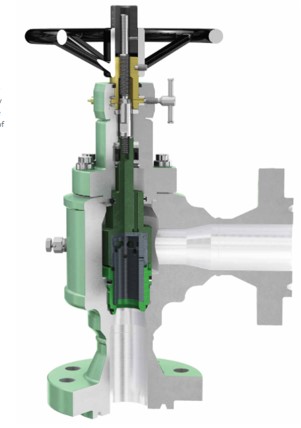
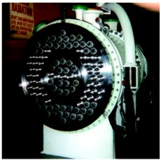
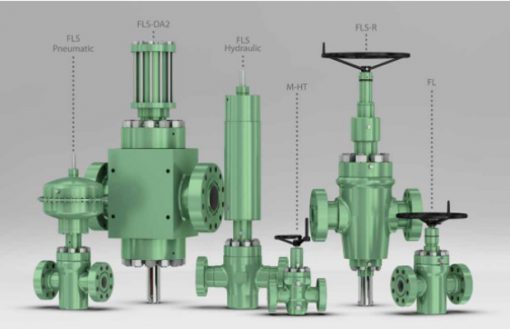
The FLS gate valve is part of the F Series of valves, which have been supplied for production and drilling service since 1958. Many of the features of the FLS are common to our original Type F gate valve, such as
        - full- and internally flushed bore and forged construction
        - metal-to-metal sealing
        - slab gate
        - design simplicity.

In other areas such as seat seals and stem seals, the FLS design takes advantage of our latest technology in materials and seal design.

The Cameron FLS gate valve is widely recognized as a high-quality valve for severe applications, available in pressure ratings from 2,000 to 20,000 psi and bore sizes from 1 13/16 to 11 in. The FLS valve is our standard valve for critical requirements, including extreme sour and subsea applications. In addition, it can be fitted with a wide range of our actuators.

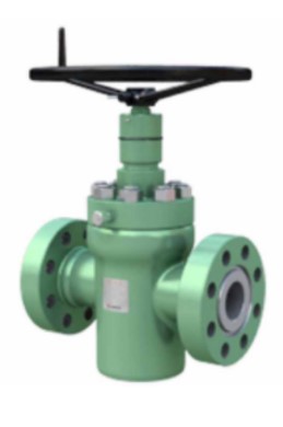
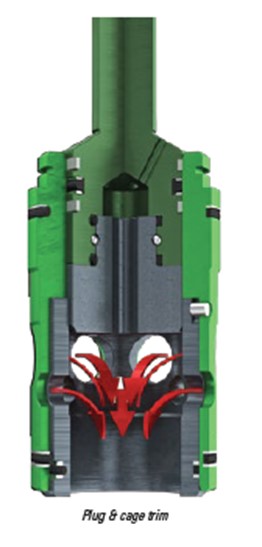
FLS Gate valve : Product and Extreme service API6A slab-style gate valve Advantages
        - Metal-to-metal sealing
        - Reliability through simplicity of design
        - Bidirectional sealing
        - Stem backseat
        - Nonelastomeric, spring-loaded, pressure-energized stem seal that requires no longitudinal preload or precise spaceout
        - Innovative seat design
        - Lip seals that perform several functions:
                 - Serving as added barrier against contaminants and debris
                 - Maintaining contact between the gate and seats, eliminating body cavity clearance while retaining downstream sealing function of the slab gate
                 - Enhancing sealing integrity at very low differential pressures, where low bearing stresses tend to limit the effectiveness of the metal-to-metal seal
        - Qualification testing to API 6A, Annex F (PR-2) and Annex I (Class II)
        - Optional torque multiplier

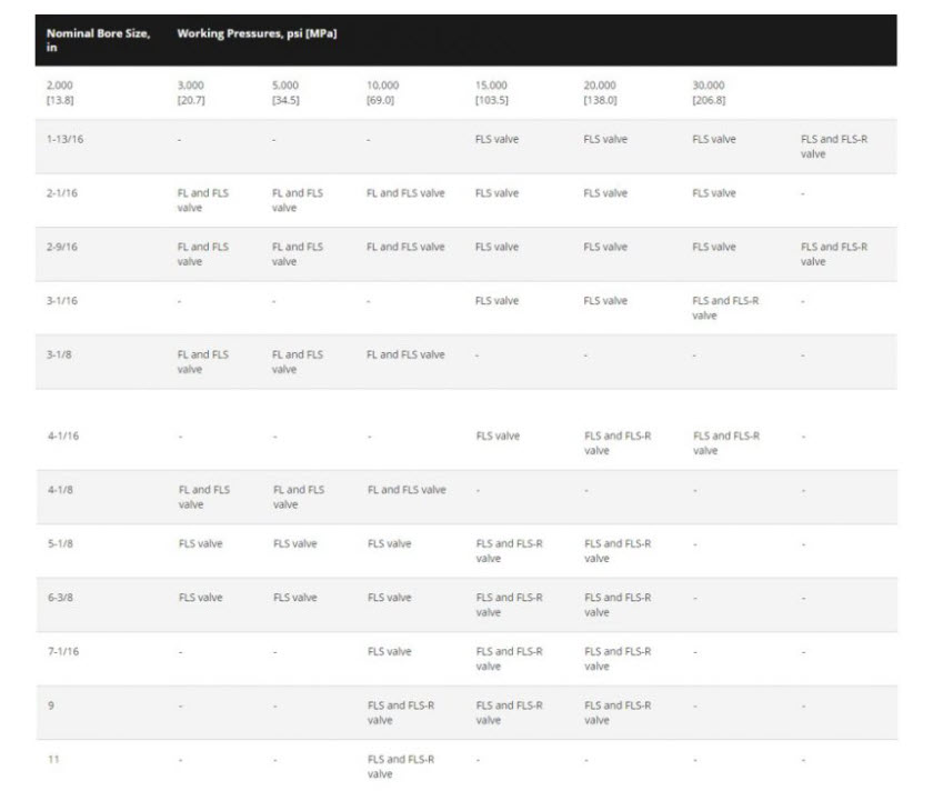
        FL, FLS, and FLS-R gate valves, this chart represents typical valves for  API material classes AA, BB, CC, DD, EE, FF, and HH (except FL) , Temperature ratings K, L, P, S, T, U, and V , Product specification levels 1, 2, 3, 3G, and 4.

Available product : Nominal Bore size vs Working pressure

Reference Project
      - PTTEP Siam : Yearly Contract Supply for API Gate valve in 2014-2015
      - PTTEP Siam : Year Contract Supply for API Gate valve in 2021-2022
https://www.gmsthailand.com/product/cameron-gate-valve-with-api6a-standard/

272
Magnetic level indicator Aurora®


Designed as an alternative and upgrade to traditional gauge devices, Magnetic Level Indicators (MLI) from Orion Instruments® are manufactured to provide accurate and reliable liquid level in a wide range of applications. Our MLI product line-manufactured globally at multiple facilities— requires minimum maintenance and eliminates common sight glass problems like vapor and liquid emission. Orion Instruments specializes in precision-engineered excellence and offers highly customized configurations and options for process environments, including those with extreme temperatures and pressures.

True Redundancy in a Single Chamber of Magnetic level indicator Aurora® .The Aurora® MLI combines Eclipse® Guided Wave Radar (GWR) and a float-actuated visual indicator to simultaneously provide both continuous and local level indication. So unique is the Orion Instruments ® dual redundancy within a singlechambered MLI that Aurora® has been granted a U.S. patent.

Technology of Magnetic level indicator Aurora®
Radar Transmitter

The Eclipse® transmitter continuously emits electromagnetic radar pulsesdirectly off the liquid surface.The on-board electronics provide a real-time level output, in addition to the external visual indicator operated by the Aurora® internal float.

Baffle Plate
The GWR probe area is separated from the freemoving float by a baffle plate.

Vertical Float
The custom float located inside the chamber is magnetically coupled to the visual indicator. The float rotates flags or moves a shuttle to visually indicate liquid tank level (as explained in more detail at right).

Visual Indication
The float positioned within the Aurora® chamber risesand falls according to levelchanges. The float contains an internal group of magnetsthat are “coupled” with magnets in the flags of the visual indicator. As the float moves, the flags rotate to expose the color of theiropposite side. The position where the flag’s color changes corresponds to a point on the measuring scale indicating true level. (The optional shuttle indicator moves parallel with the float to indicate level on the scale).


Optimum Float Performance
Orion Instruments® floats are engineered to provide the world’s best MLI performance.The 360-degree vertical placement of the magnets assures proper coupling with the flag or shuttle of the indicator, even if the float is spinning in its chamber. The magnetic assembly creates a constant Gauss rating optimized to ensure reliable performance. Float magnets are designed to function at temperatures up to +537° C (+1000° F) for years of reliable service.Special float alloys are available.

Baffle Plate
The superb float performance within the Aurora® is due in part to an angled baffle plate mounted inside the chamber.The baffle plate ➀ partitions the GWR probe area ➁ from the float area ➂ and serves as a guide to ensure both smooth float travel and proper indicator operation. Perforations along the baffleplate equalize pressure and allow free media flow within the chamber. The probe area ➁ also acts as a gasbypass zone when flashing occurs. This helps in preventing damage to the float.


Features of Magnetic level indicator Aurora®
Introduced in 1998, Eclipse® Guided Wave Radar (GWR) quickly ascended to its leading role in process level measurement. GWR is still favored throughout the industry for its easy setup, trouble-free operation, measurement accuracy, and immunity to changing process conditions.The Aurora® single chamber houses both the Eclipse® GWR probe and buoyancy float, with the former providing continuous measurement and the latter magnetically coupledto a visual indicator to provide local level indication. A flag-type indicator (or a moving shuttle) visually indicates liquid level. A variety of measurement scales and indicator flag colors are available.

Applications of Magnetic level indicator Aurora®
        - Alkylation Tanks
        - Blowdown Tanks
        - Boiler Drums
        - Condensation Tanks
        - Deaerators
        - Feedwater Heaters
        - Flash Drums
        - Gas Chillers
        - Hot Wells
        - Industrial Boilers
        - Oil-Water Separators
        - Propane Vessels
        - Storage Tanks
        - Surge Tanks
        - Vacuum Towers
https://www.gmsthailand.com/product/magnetic-level-indicator-aurora/

273
LNG ISO Tank for relocatable LNG station

Multi-layer Vacuum insulated cryogenic LNG ISO Tank is covered with double-walled shields. These are designed for efficient and cost-saving transportation.

Fixed chassis design provides excellent transportation. Even transporting in rough road, this design is strong enough to deliver in every situation.

LNG ISO container is your perfect choice for worldwide LNG transportation. The LNG ISO Tank has many customizable features. Moreover, 40-feet LNG tank is specially designed for easy transportation around the world.

LNG ISO cryogenic containers are commonly used in many countries for optimizing energy supply chains and storing liquefied natural gas in urban and rural areas. As specific customer’s requirement, customer can possibly buy or lease the containers for short or long periods. We will offer you a cost-effective solution.

Especially, LNG ISO tank and containers are designed for transportation not only on the road and rail but also in the sea and especially for international transportation.

The most outstanding function of LNG ISO Container is the ability to transport among land, railway and ocean. Gms Interneer has many partners whose enterprise passed the Ministry of Communications and national Marine Board LNG container’ test. With excellent insulation, no matter how far the transportation is, LNG ISO Container is your suitable choice in any case.

How LNG ISO Tank works ?
The main circuit of LNG ISO Tank is divided as following:

Filling

The process starts with filling LNG into the storage tank through the E-1 and through the filling valve to the tank. Especially, the pressure must be controlled in proper level. There are two main parts:
          - Bottom fill is filling LNG into the bottom of the tank containing liquid which flows directly via V-1. When LNG combines with existing LNG in the tank, it turns to faster filling. However, it will also increase the pressure of the tank.
          - Top fill is filling LNG to the top of the storage tank directly via V-2. When LNG merges with gas vapor, it becomes slower filling. Moreover, it will reduce the pressure of the tank

Pressure Build-up

To control the pressure in the storage tank, it depends on the expansion of gasified LNG liquid. PBU-1, PBU-2 Build-up coils generating pressure are controlled by V-13 which is manual shutoff. Furthermore, Some cases can be automated by regulator or on-off valve. When the pressure of the tank decreases from standard level, On-Off Valve will open until it reaches the desired pressure. Finally, the On-Off Valve will be closed. The pressure change is involved with how much you use it, for example using LNG continuously.

Safety Device

Safety Device consists of 2 sets of PRV (Pressure Relief Valve) .Each set will have 2 pairs working together which are set to the Maximum Allowable Working Pressure. If the pressure is over the setpoint, PRV will start opening. It will close until the pressure in the system is equal to the setpoint.

Instrument Device

The gauge set consists of level gauge and pressure gauge:
          - The level gauge is differential pressure type by using the difference of the pressure level of the low pressure and the high pressure. This differential pressure will push diaphragm mechanism to show the result.
          - The pressure gauge is Bourdon Type. This type is measured at the cylinder head.

LNG outlet

LNG can be used by opening the V-3 valve to distribute it through E-3. Normally, ISO container can be moved in any places and loaded back. However, filling LNG can also do in the same time but the tank pressure must be controlled stably
           - Fill on V-2 (Top Fill ) by closing V-1 (Bottom Fill), which results from the top filling may decrease the tank pressure and fill slowly. Therefore, it relies on generating pressure from the pressure control circuit.
           - In case of opening, filling on V-2 (Top Fill ) and V-1 (Bottom Fill) will continue as usual procedure by controlling the balance of both valves. However, there will be some amount of existing LNG during the filling that flows through V-3 to use in operation. This makes the amount of LNG decrease .Therefore, if taking into account the filling volume from LNG Truck, there should be a flow meter to measure the amount.
https://www.gmsthailand.com/product/lng-iso-tank-for-lng-station/

274
Magnetic level indicator Atlas™

The AtlasTM is our standard, high performance magnetic level indicator. The ATLAS is a single-chamber design, with either 2″, 2.5″, or 3″ chamber diameter, as required by the application. There are twelve basic configuration styles, including top mount models.

ATLAS magnetic level indicators are produced in a wide range of materials of construction, including exotic alloys and plastics. We also offers one of the most complete selections of process connection types and sizes for level measurement.

The ATLAS unit may be equipped with a variety of level transmitters and switches, as well as flag and shuttle indicators with or without stainless steel scales. This enables the ATLAS magnetic level indicator to be a complete level and monitoring control.

Principle
A change of level in the process tank corresponds to a similar change within the ATLAS chamber. In response to the level movement, the ATLAS float moves accordingly, actuating the flags or shuttle for visual indication.
Technology of Magnetic level indicator Atlas™

Magnetic Level Indicators (MLI) have revolutionized the global visual indication market by offering a safer, reliable, and high-visibility alternative to common gauge glass assemblies.  Utilizing a combination of proven buoyancy principles along with the benefits magnetism, MLIs can be customized to fit virtually any process connection arrangement on the vessel.

The chamber and magnetic float is available in a variety of materials and pressure ratings to accommodate the wide variety of complex process applications present in the world’s major industrial facilities.

Features of Magnetic level indicator Atlas™
         - Numerous chamber styles (or configurations) are available for each design. Consult factory for options not listed in this bulletin.
         - Complete range of level switches and level transmitters
         - Fabricated, non-magnetic chamber assembly produced in a wide range of metal and plastic materials
         - A wide range of process connections is available
         - Precision manufactured float with internal magnets and magnetic flux ring
         - ASME and EN 1092-1 process connections available
         - Flag or shuttle type indicator with stainless steel scale to measure height or percentage of level, volume or content
         - Standard float stop springs at top and bottom of chamber
         - Exceptional code qualified welding

Applications of Magnetic level indicator Atlas™
         - Feedwater heaters
         - Industrial boilers
         - Oil/water separators
         - Flash drums
         - Surge tanks
         - Gas chillers
         - Deaerators
         - Blowdown flash tanks
         - Hot wells
         - Vacuum tower bottoms
         - Alkylation units
         - Boiler drums
         - Propane vessels
         - Storage tanks
https://www.gmsthailand.com/product/magnetic-level-indicator-atlas/

275
The Jupiter® JM4 magnetostrictive level transmitter

The Jupiter® JM4 magnetostrictive level transmitter is a loop-powered 24 VDC liquid-level transmitter and is available as a direct insertion transmitter or as an external mounted transmitter onto a Magnetic Level Indicator. It relies on the position of a magnetic float which is designed precisely for the liquid to be measured. This high-accuracy device can be designed for liquid level and/or liquid-liquid interface measurement.

Principle
The Jupiter JM4 magnetostrictive level transmitter is a loop-powered 24 VDC liquid-level transmitter and is available as a direct insertion transmitter or as an external mounted transmitter onto a Magnetic Level Indicator. It relies on the position of a magnetic float which is designed precisely for the liquid to be measured. This high-accuracy device can be designed for liquid level and/or liquid-liquid interface measurement.

Technology of JM4 magnetostrictive level transmitter
Magnetostriction

A low-energy pulse, generated by the JUPITER electronics, travels the length of the magnetostrictive wire. A return signal is generated from the precise location where the magnetic field of a float intersects the wire. A timer precisely measures the elapsed time between the generation of the pulse and the return of the acoustic signal.  Each cycle occurs ten times per second, providing real-time and highly accurate level data.

How magnetostriction works
LOW-VOLTAGE PULSE

On-board electronics send a low-voltage electrical pulse down the magnetostrictive wire at the speed of light, ten times per second.

MAGNETS
Magnets contained within the float focus their energy toward the wire at the precise location of the liquid level.

PIEZOELECTRIC CRYSTALS
The mechanical wave is converted back into electrical energy by two piezoelectric crystals. The on-board electronics interpret the time-of-flight data and indicate the position of the float magnets.

TWIST
Interaction between the magnetic field, electrical pulse, and magnetostrictive wire cause a slight mechanical disturbance in the wire that travels back up the probe at the speed of sound.


Features of JM4 magnetostrictive level transmitter
         - 4-button user interface and graphical LCD display provide enhanced depth of data, indicating on-screen waveforms and troubleshooting tips.
         - 4-20 mA output
         - Rotatable housing can be dismantled without depressurising the vessel via “Quick connect/disconnect” probe coupling.
         - Ergonomic dual compartment enclosure
         - Simple set-up and configuration
         - Smart Probe Technology
         - Easy attachment to an MLI
         - Direct insertion for a wide variety of vessels and applications

Application of JM4 magnetostrictive level transmitter
Chemical

         - Chemical injection
         - Chemical injection skids
         - Condenser
         - Deionization tanks
         - Distillation columns
         - Distillation towers
         - Liquid-Liquid extraction
         - Neutralization
         - Quench Tower/Settler
         - Reboiler
         - Reflux drum
         - Scrubber vessels
         - Steam drums for chemical industry

Natural Gas
         - Chemical injection skids
         - Compressor Scrubber
         - Compressor Waste Liquid
         - Gas Dehydration
         - Natural gas separators
         - NGL recovery & Storage
         - Separators
         - Sour gas treatment
         - Sulfur Recovery
         - Vapor recovery unit

Petroleum Refining
         - Alkylation tanks
         - Catalytic reformers
         - Catalytic strippers
         - Crude desalting
         - Crude Dewatering
         - Diesel fuel storage tanks
         - Distillation columns
         - Distillation towers
         - Gun-barrel separators
         - Horizontal separators
         - Hydrocracking
         - Hydrodesulfurization
         - Isomerization
         - Reboiler
         - Separator boots
         - Solvent extraction
https://www.gmsthailand.com/product/jm4-magnetostrictive-level-transmitter/

276
Cameron choke valve – flow control industry standard

Cameron’s choke valve is designed to provide precise flow control throughout their entire operating range, with a well-proven track record in the field :

Overview – Control Choke valve
Cameron’s control choke valve is designed to provide precise flow control throughout their entire operating range, with a well-proven track record in the field :
        - Control choke valve is suitable for a wide variety of applications, including production, injection, artificial lift, flowback, storage, etc.
        - Commonly installed on Christmas trees, manifolds, line heaters, offshore platforms, FPSOs, and other equipment, providing precise flow control under severe service conditions.
        - Available with plug & cage, external-sleeve or multistage trim types.
        - Multiple flow characteristics, including ‘linear’ or ‘equal percentage’, with special trim solutions available in response to specific challenges.
        - Special trim solutions include ultra-low Cv, low noise, and well cleanup types.
        - Control chokes offer a complete solution from startup to late life conditions, with the flexibility to easily retrofit various trim types as conditions evolve.
        - Available in manual and actuated configurations, including multiple actuator types.

Application of Cameron’s Control Choke Valve
        - Selection of the correct trim size and type is vital to the successful and reliable operation of a choke. Cameron offers a computer-based choke sizing program to optimize choke sizing and selection for you.
        - Based on flow and pressure requirements of the application, the program analyzes and specifies the optimal choke size and trim configuration.
        - Features of the program include
        - capability to size a large number of chokes and flow conditions
        - modular sizing program structure that enables the addition of new choke and choke trim data updates as needed
        - graphics capabilities
        - project worksheet and Cv curve printouts
        - choke sizing per ANSI/ISA S75.01 specifications
        - flow testing per ANSI/ISA S75.02 specifications
        - noise prediction and testing per ANSI/ISA S75.07 specifications.

External Sleeve Control Choke for low-capacity, high-pressure-drop applications
       - The external sleeve control choke has a sleeve that throttles the flow on the external diameter of the ported cage. The external sleeve trim is particularly suited for low-capacity/high pressure-drop applications. The external sleeve is designed specifically for severely erosive service where the combination of high pressure drops and high sand concentrations can reduce the life of a choke.
        - Available in various sizes ranging from CC15 to CC80 choke models.
        - Tungsten carbide-lined external sleeve and solid tungsten carbide cage/seat provide optimum wear resistance in erosive conditions.
        - Metal body-to-bonnet gasket for absolute pressure containment.
        - Reverse angle external sleeve improves flow dynamics within the trim.
        - Self-flushing, pressure-balanced ports reduced stem loads and actuator output requirements.
        - Heavy-duty thrust bearings reduce operating torque.
        - Pressure-balance seals are a key feature of the pressurbalanced trim arrangement, reducing operating forces and enabling greater ease of adjustment.

Features
        - Large visual indicator provides position in 1/64 in (bean) as standard.
        - External grease port lubricates threads and bearings.
        - Stem lock maintains set position.
        - Bleed plug assembly vents pressure before disassembly.
        - Antirotation key translates rotation from the drive bushing into linear movement of the lower stem/flow plug assembly.
        - Two-piece stem is threaded and locked, and is removed from wellbore fluids.
        - Large annulus area reduces the risk of body and trim erosion caused by high velocities.

All control chokes are available in manually operated or actuated models. Custom-designed trim components to suit a wide variety of Cv capacities and flow characteristics also are available

Plug & Cage Control choke
        - The plug and cage control choke uses the plug as the controlling element and throttles the flow on the internal diameter of the ported cage. The ports in the cage are sized and arranged to give the most appropriate combination of control and flow capacity for each application.
        - A major consideration when sizing the choke is the ability to closely manage well startup while optimizing capacity toward the end of well life to maximize production.
        - The plug and cage design is highly optimized and incorporates the largest-possible flow area, making it ideal for high-capacity applications. Plug and cage chokes also are constructed with a solid tungsten carbide plug tip and inner cage for extended resistance to erosion. These valves may further be configured with a solid tungsten carbide wear sleeve in the outlet of the body to provide enhanced protection in sandy service.

This trim also includes a thick metal outer cage to ensure maximum protection against solid impacts from debris in the flow. The combined result is a versatile, robust, erosion-resistant trim with suitability for a broad range of challenging applications.

        - Available in various sizes ranging from CC15 to CC80 choke models.
        - Tungsten carbide plug tip in conjunction with solid tungsten carbide cage optimizes wear resistance in erosive conditions.
        - Metal body-to-bonnet gasket for absolute pressure containment.
        - Fully guided plug reduces side loading and vibration.
        - Self-flushing, pressure-balanced ports reduce stem loads and actuator output requirements.
        - Heavy-duty thrust bearings reduce operating torque.
        - Pressure-balance seals are a key feature of the pressure-balanced trim arrangement, reducing operating forces and enabling greater ease of adjustment.
        - Metal outer cage protects from impact damage.

The control choke model
CC15 Control Choke Valve


CC20 Control Choke Valve


CC30 Control Choke Valve

High Temp and High Pressure Application

https://www.gmsthailand.com/product/cameron-control-choke-valve/

277
What is LNG Storage Tank? and what it’s used for?

In the shipping sector, liquefied natural gas (LNG) has firmly established itself as the fuel of choice for the future, according to a wide range of participants. Despite this upbeat outlook, one of the most significant barriers to switching to natural gas is the expensive initial investment required for LNG storage facilities. Supplier is continuing to investigate innovative ways of integrating technology in order to provide cost-effective storage solutions for gas-fueled boats of any size and LNG installed volume, regardless of their fuel source.

Shipping is a truly global business with fierce competition on an ongoing basis. Increased public pressure to reduce the sector’s environmental effect only serves to increase customers’ desire to lower their expenses. In order to save money and stay one step ahead of the competition, it may be necessary to implement innovative new solutions or repurpose existing technology from other industries. The latter method is often less complicated, involves less risks, and results in a shorter time to market. The evaluation of current technologies and their cost drivers, as a consequence, may aid in the creation of strategies for overcoming implementation roadblocks. Of course, each Supplier solution takes into account the unique needs of each customer, but this research outlines a few of the ways in which Supplier may help more customers in realizing the environmental and economic benefits of LNG.

Installations and equipment for liquefied natural gas – EN 1473
Cryogenic Liquid Vacuum Storage Tank

Euronorm It is the European standard EN 1473 Installation and equipment for liquefied natural gas, which serves as the overarching document for the design, building, and operation of all onshore LNG facilities. It includes installations for liquefaction and regasification, as well as storage facilities, which are often referred to as tanks in the industry. Environment compatibility, safety needs, risk assessments, and safety engineering are all addressed in detail in EN 1473, which specifies terminology and imposes standards to be taken into consideration throughout the design process. These LNG facilities are specified in detail in the standard and in Annex G: – LNG export terminal; – LNG receiving terminal; – LNG peak-shaving plants; and – LNG satellite plants.

Some parts of this standard have a direct impact on the design and construction of concrete tanks, while others have a less direct impact. This includes suggestions on how to evaluate safety and environmental compatibility, which are included in Chapter 4, for example. A thorough environmental impact assessment (EIA) must be carried out after the site has been determined. It is necessary to do this evaluation in order to determine the total amount of solids, liquids, and gases released by the facility during both regular operation and accidents. It is essential that plants be built in such a manner that gas is not constantly flared or vented, but is instead recovered to the greatest extent feasible, and that hazards to persons and property both within and outside the facility are minimized to a level that is widely considered acceptable. The study of the site may provide load scenarios that are important for the design, such as tsunamis or blast pressure waves,amongst other possibilities. It is necessary to include information on the existence of karst, gypsum and swelling clays in geological and tectonic soil surveys, as well as the susceptibility of the soil to liquefaction, the physical formation process, and the possibility for seismic activity in the future.

When constructing an LNG plant, it is necessary to do a risk assessment. The guidance in Annexes I, J, and K (which are given only for informational reasons) pertains to establishing frequency ranges, classes of consequence, degrees of risk, and acceptance criteria, among other things. A risk category is given to the plant based on a study of frequency ranges and consequence classes, and the plant is assigned to one of three risk categories. If the risk is acceptable, it must be lowered to a level that is as low as reasonably practicable (ALARP), if it is unacceptable, it falls into one of the categories listed above. In the annexes, the values specified are minimum requirements that may be increased by national laws or project specifications.

When doing a hazard and operation study (HAZOP), risk assessment is often included, but other methods are also allowed, such as failure mode and effect analysis (FMEA), event tree method (ETM), and fault tree method (FTM). It is necessary to categorize plant systems and components based on their relevance to safety within the scope of the risk assessment. Here, there is a division into two categories: class A, which includes systems that are critical to plant safety or protection systems that must be kept operational to ensure a minimum level of safety; and class B, which includes systems that perform functions that are critical to plant operation or systems whose failure could result in a major impact on the environment or create an additional hazard.

Sections 6.3 and 6.4 are particularly important for the design of concrete storage tanks, respectively. Section 6.3 and Annex H include specifics and illustrations of the different tank types, information that is complemented by the more comprehensive requirements of EN 14620 Part 1 (European Standard for Pressure Vessels). Because it covers spherical tanks as well as concrete tanks with both the main and secondary containers constructed of prestressed concrete, EN 1473 goes farther than EN 14620 in terms of the information that it provides. 6.4 defines design principles, which include criteria for fluid-tightness, maximum and minimum pressures, tank connections, thermal insulation, instrumentation, heating, and liquid level restrictions, among other things. These principles allow for the development of design criteria for the architecture of the facility, the minimum distance between tanks, and the consideration of potential sources of danger such as fire or blast pressure wave, among other things.

Construction of LNG Tanks – EN 14620 The European Standard EN 14620, which specifies the design and manufacture of site-built vertical, cylindrical, flat-bottomed steel tanks for the storage of refrigerated, liquefied gases with operating temperatures ranging from zero degrees Celsius to one hundred and sixty degrees Celsius, is divided into five parts:

Part 1: Overarching Concepts
Part 2: Components made of metal
Part 3: Components made of concrete
Part 4: Components of the insulation
Part 5: Testing, drying, purging, and cooling-down procedures.

Types of LNG Storage Tanks

Type of LNG tanks

Liquefied gas storage tanks are classified according to their kind and size according to a variety of standards and rules that vary in terms of when they were issued as well as the amount of information they provide. The two German standards, DIN EN 1473 and DIN EN 14620, are even diametrically opposed in terms of the language they use. This section will make use of either the terminology found in the British counterpart, BS EN 1473, or the terms found in API 625. BS EN 1473 is the British equivalent of API 625. From a practical standpoint, the term “containment tank system,” as used in API 625, seems to be the most suitable, since the many, but coordinated, components work together to form a cohesive system as a result of their interaction. According to the standards EEMUA, BS 7777, EN 1473, EN 14620- 1, NFPA 59A, and API 625, containment tank systems may be classified as single, double, or complete containment tank systems. There is one additional tank type that is described in more depth in the European standards EN 1473 and EN 14620, and that is the membrane tank.

Until the 1970s, the only kind of tank that was constructed was the single-wall tank. It was the hazard scenarios resulting from abnormal actions such as failure of the inner tank, fire, blast pressure wave, and impact that inspired the subsequent further development of the various types of tanks or tank systems, and the associated requirements placed on the materials and construction details. Because of the dangers that a tank failure poses to the surrounding regions, it is essential to choose the appropriate kind of tank system.

It will be shown, using the failure of the inner container, the consequences of such a failure on the tank as a whole and its surroundings for three widely used tank systems. It will also be discussed how these three tank systems have evolved over time.
https://www.gmsthailand.com/blog/what-is-lng-storage-tank/

278
สำนักพิมพ์ ส.ส.ท. สมาคมส่งเสริมเทคโนโลยี (ไทย-ญี่ปุ่น)


เริ่มดำเนินการจัดพิมพ์หนังสือตั้งแต่ปี พ.ศ. 2516 ซึ่งเป็นปีที่ก่อตั้งสมาคมส่งเสริมเทคโนโลยี (ไทย-ญี่ปุ่น) โดยมีวัตถุประสงค์ดังนี้
ส่งเสริมให้มีการเขียน แปล และเรียบเรียงหนังสือวิชาการทางด้านเทคโนโลยีสาขาต่างๆ ด้านการจัดการและการบริหารธุรกิจ อุตสาหกรรมเป็นภาษาไทย เพื่อให้นักศึกษาตั้งแต่ระดับอาชีวศึกษาขึ้นไป ช่างเทคนิค วิศวกร และผู้บริหารระดับต่างๆ ได้มีหนังสือประกอบการเรียนและการทำงานอย่างมีประสิทธิภาพเพื่อให้ครู-อาจารย์ นักวิชาการ นักปฏิบัติการและผู้เชี่ยวชาญในวงการอุตสาหกรรมได้มีโอกาสเผยแพร่ผลงานของตนให้แพร่หลาย เพื่อให้เกิดการส่งเสริมและการเผยแพร่เทคโนโลยีออกไปสู่ทั้งภาคการศึกษาและภาคอุตสาหกรรม เพื่อการพัฒนาประเทศดังความมุ่งมั่นที่ว่า "ส.ส.ท. เผยแพร่วิทยาการ สร้างฐานเศรษฐกิจ"
https://www.tpa.or.th/tpapublishing/


สำนักพิมพ์ ส.ส.ท.
5-7 ซอยสุขุมวิท 29 ถนนสุขุมวิท แขวงคลองเตยเหนือ เขตวัฒนา กรุงเทพฯ 10110
โทร. 0-2258-0320 (6 เลขหมายอัตโนมัติ), 0-2259-9160 (10 เลขหมายอัตโนมัติ)
ติดต่อสำนักพิมพ์ [email protected]
ติดต่อสั่งซื้อหนังสือได้ที่ www.tpabook.com

facebook fanpage
www.facebook.com/technologybook
www.facebook.com/tpabook
www.facebook.com/mathtpa
https://www.tpa.or.th/tpapublishing/contact.php

279
PUREMEG Monoethylene glycol (MEG) reclamation and regeneration system


Monoethylene glycol (MEG) reclamation is widely used by the oil and gas markets in wellheads and pipelines to prevent hydrate formation at pipeline conditions. In offshore deepwater gas production facilities, where the exposure to lower temperatures in subsea pipelines is common , MEG is used for hydrate inhibition.

Overview –  PUREMEG Monoethylene glycol (MEG) reclamation and regeneration system
Minimize MEG deterioration and losses and reduce operating and environmental costs

Monoethylene glycol (MEG) reclamation is one of the most commonly used reagents for hydrate inhibition in production pipelines. It is recovered and reinjected to minimize the operating and environmental costs associated with MEG replacement and disposal.

PUREMEG MEG reclamation and regeneration systems not only regenerate the MEG by boiling off the pipeline water, they also remove salts and other solids to achieve the required outlet glycol purity. Dissolved salts in formation water, pipeline production chemicals, and pipe scale all have the potential to scale or foul both subsea and topside processing equipment. This MEG recovery system is an essential component of pipeline flow assurance.

Improve operational efficiency, increase plant availability, and maintain asset integrity
In addition to our reclamation technology, we provide everything from customized site support contracts covering training, installation, commissioning, and startup to long-term operational assistance, data acquisition, conditional monitoring, and predictive maintenance services.


PUREMEG Monoethylene glycol (MEG) reclamation and regeneration system

Advantages
      - The system provides effective and proven salt removal.
      - Low solids levels in the recycle loop protect the most expensive and vulnerable parts of the system from abrasion, erosion, and fouling, which reduces maintenance and increases plant availability.
      - Low solids levels in the recycle loop protect the most expensive and vulnerable parts of the system from abrasion, erosion, and fouling, which reduces maintenance and increases plant availability.
      - The technology significantly reduces Monoethylene glycol (MEG) reclamation losses and produces a wastestream suitable for marine disposal by separating salt from brine.
      - Solids removal is achieved without the use of centrifuges, unlike other systems on the market. This avoids use of expensive, high-maintenance equipment and prevents oxygen contamination of the Monoethylene glycol (MEG) reclamation. Oxygen is a main contributor to MEG degradation and material corrosion within reclamation systems, affecting both opex and the life of the plant.
      - The MEG reboiler is designed to avoid hydrocarbon foaming and the fouling of packing associated with conventional systems.
      - The proprietary divalent salt removal system is capable of handling a diverse range of water chemistries, solids loadings, and particle-size distributions.
      - The dedicated reaction vessel optimizes crystal growth in the precipitation of divalent salts. Crystal size and shape directly influence the performance of downstream separation and drying processes.
     - A wash step is included as part of the divalent salt removal system, enabling MEG recovery and reducing opex; the salt discharge can be dried for easier handling and disposal


Monoethylene Glycol (MEG) Reclamation & Regeneration

Five-step process to regenerate MEG and remove salts
The PUREMEG system is configured with either a full-stream or slipstream process. Full stream both regenerates and removes salts from the rich MEG feed. Slipstream has full-feed MEG regeneration, with a portion of the lean of Monoethylene glycol (MEG) reclamation. Our experts can advise you which option best suits your process requirements. In either case, the process comprises five steps: pretreatment, MEG regeneration, flash separation, salt management, and divalent salt removal.

1) Pretreatment
In the pretreatment stage, the rich MEG—containing some dissolved gas and hydrocarbon liquids—is heated and passed through a three-phase separator vessel. The gas is flashed to flare and liquid hydrocarbons are sent to the condensate recovery system. The treated MEG is sent either to storage or the downstream process.

2) MEG regeneration
MEG regeneration is conducted in a reflux distillation column. For a slipstream process, the column operates off the low-pressure flare backpressure and is provided with a pump-around heating loop. For a full-stream system, the distillation column operates under vacuum conditions.

The lean MEG produced at the bottom of the column is pumped to storage for reuse. For the slipstream service, a portion of the lean MEG is sent for reclamation. The vaporized water passes overhead where it is condensed and collected in the reflux drum. A portion of the water is returned to the distillation column to provide reflux while the remainder is routed to water treatment. Residual hydrocarbons in the system are generally associated with this produced water stream, and we provide a wide range of water treatment systems capable of meeting local environmental legislation for discharge.

3) Flash separation (reclaimer)
In the flash separator, the rich MEG stream (full-stream reclamation) or lean MEG stream (slipstream reclamation), consisting of water and MEG with dissolved salts, is brought into contact with a hot recycled stream of concentrated MEG. The flash separator operates under vacuum conditions to maintain process temperatures below the degradation temperature of MEG. The feed MEG and water are vaporized and exit through the top of the flash separator. These vapors either pass to the MEG distillation column for regeneration (full-stream service) or are condensed and sent to lean MEG storage (slipstream service). The monovalent salt components, primarily sodium chloride, precipitate in the flash separator. They fall via gravity through a column of brine and are collected in the brine-filled salt tank.

4) Salt management
The salt tank serves two primary functions. The first is to condition the salt levels for optimal performance of the salt separation process. The second is to provide a surplus of salt for converting freshwater makeup to saturated brine. Salt is removed from the brine by a hydrocyclone to produce a slurry suitable for a landfill or for redissolving for marine disposal.

5) Divalent salt removal
Divalent salts (typically calcium, magnesium, and iron but also barium and strontium) cannot be precipitated out in the flash separator. Instead they accumulate in the process, which has an impact on system operability. For a slipstream process, the salts are often a cause of scaling within the reboiler. Removing the salts by MEG blowdown can be cost-prohibitive once disposal and replenishment costs are considered.

The divalent salt removal system precipitates out the salts by chemical reaction to form insoluble salts. Crystal size and shape directly influence the performance of the downstream filter. A dedicated reactor vessel is provided to control the temperature, time, and concentration for optimal crystal growth and morphology. Both sodium carbonate and sodium hydroxide are used for the chemical reaction to account for variations in feed conditions. The crystals, together with any other solids such as pipe scale and sand, are removed by filtration. Typically a dynamic crossflow filter is used for this service because of its tolerance for a wide range of particle sizes and distribution. The filter produces a clean MEG stream, which is returned to the process, and a concentrated slurry or cake, which is washed to recover any residual MEG. The produced slurry or cake can be further dried to provide a waste product that is easy to store and handle.

Typical PUREMAG system with full-stream reclamation

https://www.gmsthailand.com/product/puremeg-monoethylene-glycol-meg-reclamation-and-regeneration-system/

280
ศูนย์แปลและล่าม สมาคมส่งเสริมเทคโนโลยี (ไทย-ญี่ปุ่น)


บริการแปลเอกสารและล่าม
บริการแปลเอกสารและล่ามภาษาญี่ปุ่น ไทย จีน อังกฤษ ฯลฯ โดยบุคลากรที่มีความชำนาญพร้อมรับรองเอกสารสำหรับใช้ติดต่อกับหน่วยงานราชการหรือสถานทูต

บริษัทชั้นนำที่ให้ความไว้วางใจองค์การส่งเสริมการค้าต่างประเทศของญี่ปุ่น (JETRO)
       - สมาคมความร่วมมือทางเศรษฐกิจ ญี่ปุ่น-ไทย (JTECS)
       - บริษัท โตโยต้า มอเตอร์ ประเทศไทย จำกัด
       - บริษัท ไทยยามาฮ่ามอเตอร์ จำกัด
       - บริษัท ตรีเพชรอีซูซุเซลล์ จำกัด
       - บริษัท คาลบี้ ธนาวัธน์ จำกัด
       - บริษัท เอปสัน พรีซิชั่น (ไทยแลนด์) จำกัด
       - บริษัท ซีพีแรม จำกัด
       - บริษัท คาเนโบ คอสเมติกส์ (ประเทศไทย) จำกัด
       - Japan Quality Assurance Organization (JQA)

ขั้นตอนการใช้บริการ
1. ดาวน์โหลดแบบฟอร์มการประเมินงานแปลและล่าม พร้อมส่งต้นฉบับสำหรับแปล หรือเนื้อหางานล่ามและแผนที่ มาทางโทรสารหรืออีเมล
2. รอรับใบยืนยันการใช้บริการพร้อมชำระเงิน
3. เมื่อท่านชำระเงินแล้ว ทางศูนย์แปลและล่ามจึงจะเริ่มดำเนินงานและส่งมอบงานตามกำหนด

ขั้นตอนการดำเนินงานแปล
1. ส่งเอกสารที่ต้องการแปล พร้อมแนบแบบฟอร์มประเมินงานแปลมาที่ศูนย์แปล ชั้น 2 ฝ่ายโรงเรียนภาษาหรือทางอีเมล [email protected]
2. ทางศูนย์แปลจะดำเนินการประเมินราคาค่าแปลเอกสาร ตามจำนวนตัวอักษร และความยากง่ายของเอกสารและจะกำหนดระยะเวลาที่คาดหวังว่างานจะเสร็จสมบูรณ์ พร้อมส่งใบเสนอราคาค่าแปลเอกสารแก่ลูกค้า **ทางศูนย์แปลฯ ไม่รับจัด ART WORK ใดๆทั้งสิ้น**
3. ลูกค้าสามารถยืนยันการดำเนินการแปลได้ภายใน 7 วัน โดยนับจากวันที่ในใบเสนอราคา (หากทางศูนย์แปลไม่ได้รับการยืนยันภายใน 7 วัน จะดำเนินการยกเลิกใบเสนอราคาทันที และขอสงวนลิขสิทธิ์ในการทำลายเอกสารที่ลูกค้าส่งมา)
4. กรุณายืนยันการดำเนินการงานแปล โดยลงนามผู้อนุมัติดำเนินการแปล, วันที่ และวิธีการชำระเงินในใบเสนอราคา พร้อมทั้งชำระค่าแปลเต็มจำนวน
(ทางสมาคมได้รับการยกเว้นการหักภาษี ณ ที่จ่าย 3 % และราคานี้รวม VAT 7 % แล้ว)
5. หลังจากที่ทางศูนย์แปลได้รับชำระเงินเรียบร้อยแล้ว จึงจะเริ่มดำเนินการแปล **การประเมินระยะเวลางานเสร็จ (ที่แจ้งในใบเสนอราคา) จะเริ่มนับหลังจากชำระเงินเรียบร้อยแล้ว
6. หากทางลูกค้าได้ตกลงให้ทางศูนย์แปลดำเนินการแปลเรียบร้อยแล้ว แต่ภายหลังต้องการติดต่อขอยกเลิก ทางลูกค้าจำเป็นต้องชำระค่า Cancellation Charge เป็นจำนวน 50 % ของใบเสนอราคา
7. งานแปลที่รับไปแล้วจะมีผลรับผิดชอบภายใน 7 วันเท่านั้น

ขั้นตอนการดำเนินงานล่าม
1. ส่งข้อมูล รายละเอียด และแผนที่สถานที่ทำงานล่าม พร้อมแนบแบบฟอร์มประเมินงานล่ามมาที่ศูนย์แปล ชั้น 2 ฝ่ายโรงเรียนภาษาหรือทางอีเมล [email protected]
2. ทางศูนย์แปลฯ จะดำเนินการประเมินราคาค่าล่าม และกำหนดค่าใช้จ่ายที่จำเป็นเพิ่มเติม (เช่น ค่าเดินทาง, ค่าอาหาร, ค่าที่พัก) รวมถึงค่าล่วงเวลาการทำงานด้วย
3. ในส่วนของค่าล่วงเวลาการทำงาน (OT) นั้น ลูกค้าสามารถมอบให้แก่ล่ามโดยตรง (ไม่ผ่านศูนย์แปลฯ ส.ส.ท.)
4. ลูกค้าสามารถยืนยันการจ้างล่ามได้เมื่อทางศูนย์แปลฯ แจ้งว่าสามารถหาล่ามที่เหมาะสมสำหรับงานนั้นๆ ได้
5. ลูกค้าสามารถยืนยันการจ้างล่ามโดยการ “ลงนามผู้อนุมัติดำเนินการล่าม” ในใบเสนอราคา พร้อมทั้งชำระค่าล่ามเต็มจำนวน
(ทางสมาคมฯ ได้รับการยกเว้นการหักภาษี ณ ที่จ่าย 3 % และราคานี้รวม VAT 7 %แล้ว)
6. หลังจากทางศูนย์แปลฯ ได้รับชำระเงินครบเต็มจำนวนแล้ว จึงจะดำเนินการส่งมอบล่ามให้แก่ลูกค้าโดยกำหนด วันเวลา พร้อมทั้งสถานที่นัดพบ โดยรายละเอียดการนัดพบจะตกลงกับลูกค้าอีกครั้ง
7. หากทางลูกค้าได้ตกลงให้ทาง ส.ส.ท. จัดหาล่ามเรียบร้อยแล้ว แต่ภายหลังต้องการติดต่อขอยกเลิก ทางลูกค้าจำเป็นต้องชำระค่า Cancellation Charge เป็นจำนวน 50 % ของใบเสนอราคา หรือหากใช้ล่ามไม่ตรงตามรายละเอียดที่กรอกลงในแบบฟอร์มประเมินงานล่าม ทางสมาคมฯ จะขอยกเลิกการใช้บริการล่ามโดยทันที และลูกค้าจำเป็นต้องชำระค่า Cancellation Charge เป็นจำนวน 50 % ของใบเสนอราคา
https://www.tpa.or.th/tic

281
Glycol Dehydration Systems for water removal


Schlumberger Glycol dehydration systems remove water vapor from natural gas, which helps prevent hydrate formation and corrosion and maximixes piplines efficiency.

Overview –  Glycol dehydration systems
Efficient removal of water and impurities from natural gas streams

Our triethylene glycol dehydration system is among the most widely used in the oil and gas industry because of low operating costs and relatively low capex. Glycol dehydration systems are not only efficient at removing water from a natural gas stream, they also remove benzene, toluene, ethylbenzene, and xylene (BTEX) as well as other volatile organic compounds (VOCs).

In natural gas systems, removing water vapor reduces pipeline corrosion and eliminates line blockage caused by hydrate formation. The water dewpoint needs to be below the lowest pipeline temperature to prevent free-water formation.

Using amine treatment to remove acid gases results in water-saturated gas that must be dehydrated before entering the pipeline. Most product specifications require the maximum quantity of water in the gas to be 4 to 7 lbm/MMcf.

Advantages
         - Suitable for a wide range of flow, pressure, and temperature conditions
         - Lower operating costs than conventional desiccants
         - Lower capex than solid bed systems
         - Custom and standard units, which can employ either bubble cap or structured packing
         - Reduced manufacturing and commissioning times for standard system designs
         - Easily packaged hybrid systems (amine packaged with glycol dehydration systems) for small to large gas sweetening requirements

Application of  Glycol dehydration systems
In our glycol dehydration system, wet gas enters a tower at the bottom and flows upward. Dry glycol flows down the tower from the top, from tray to tray or through packing material.


Our special bubble cap configuration maximizes gas-glycol contact, removing water to levels below 5 lbm/MMcf. Advanced systems can be designed to achieve levels less than 1 lbm/MMcf.


The dehydrated gas leaves the tower at the top and returns to the pipeline or goes to other processing units. The water-rich glycol leaves the tower at the bottom and goes to the reconcentration system, where it is filtered to remove impurities and heated to 400 degF [204 degC]. Water escapes as steam, and the purified glycol returns to the tower where it again contacts wet gas.

The entire system operates unattended. Controllers monitor pressures, temperatures, and other aspects of the system to maximize safety and efficiency.
https://www.gmsthailand.com/product/glycol-dehydration-systems-3/

282
โรงเรียนภาษาและวัฒนธรรม สมาคมส่งเสริมเทคโนโลยี (ไทย-ญี่ปุ่น)


โรงเรียนภาษาและวัฒนธรรม สมาคมส่งเสริมเทคโนโลยี (ไทย-ญี่ปุ่น)
School of Language & Culture, Technology Promotion Association (Thailand-Japan)
https://www.tpa.or.th/slc

ภาษาญี่ปุ่นชั้นต้น  ( เรียนด้วยอักษรญี่ปุ่น )
เน้นการฝึกฝนทักษะทั้ง 4 ด้าน คือ ฟัง พูด อ่าน เขียน โดยอาจารย์ชาวไทยสอนไวยากรณ์และคำศัพท์ อาจารย์ชาวญี่ปุ่น สอนสนทนาและอักษรคันจิ
คอร์ส  JB01-JB03  :  https://www.tpa.or.th/slc/download/b-s-jp_JB01_JB03.pdf
คอร์ส  JB04-JB06  :  https://www.tpa.or.th/slc/download/b-s-jp_JB04_JB06.pdf
คอร์ส  JB07-JB09  :  https://www.tpa.or.th/slc/download/b-s-jp_JB07_JB09.pdf
คอร์ส  JB10-JB12  :  https://www.tpa.or.th/slc/download/b-s-jp_JB10_JB12.pdf
คอร์สภาษาญี่ปุ่นเร่งรัด  :  https://www.tpa.or.th/slc/download/b-s-jp_i_JI01-JI04.pdf


283
Cyclotech B Series deoiling hydrocyclone


CYCLOTECH B Series deoiling hydrocyclone technologies represent the state of art in produced water treatment technology, a third-generation geometry optimizing the critical balance between oil-removal efficiency and capacity. Leveraging a globally installed based on both onshore and offshore facilities, the technologies ensure that peak separation is achieved in the most cost-effective and space efficient manner.

Overview – Cyclotech B Series Deoiling hydrocyclone
Balancing efficiency and throughput capacity in a reliable, wear-resistant separation solution


Deoiling hydrocyclone technologies represent the state of the art in produced water treatment, optimizing the critical balance between oil-removal efficiency and throughput capacity. Achieving this balance yields peak separation in the most cost-effective and space-efficient manner. These technologies have a global track record in onshore and offshore facilities.

CYCLOTECH Cyclonic Separation Technologies

Having no moving parts, CYCLOTECH B Series hydrocyclone technologies achieve liquid-liquid separation using a pressure drop across the unit. Their liners are manufactured from a range of wear-resistant materials, including tungsten carbide or reaction-bonded silicon carbide. An advanced ceramic that extends wear life up to 10 times beyond a standard duplex stainless steel liner is also available.

B Series technologies treat waterstreams containing up to 2,000 mg/L of oil to meet a discharge-water oil content of 30 mg/L—or more commonly, stretch targets as low as 15 mg/L.

With special features
        - Improved reliability – Use of no moving parts and wear-resistant materials
        - Smaller footprint – Compact design uses less space
        - More efficiency – Retrofit capability increases capacity and separation performance

CYCLOTECH Cyclonic Separation Technologies

Application of Cyclotech B Series Deoiling hydrocyclone
Operating with no moving parts, B Series technologies achieve liquid-liquid separation using a pressure drop across the unit. Oily water is forced under pressure into the inlet section of the liner via a tangential inlet port. This pressure, together with narrow cyclone diameter, causes the fluid to spin at high velocity, creating a high gradial acceleration field. Oil, the less-dense liquid, is forced to the axial center of the hydrocyclone to form a thin oil core. Through internal hydrodynamic forces and external differential pressure control, this oil core is removed via the reject ports of the hydrocyclone liners; the clean water flow is discharged from the cyclone underflow.
https://www.gmsthailand.com/product/cyclotech-b-series/

284
Amine gas treating system with field-proven


Hydrogen sulfide, Carbon dioxide,and other contaminations are often found in natural gas streams. Amine gas treating systems remove these contaminations so that the gas is suitable for transportation and use.

Overview – Amine gas treating systems
Prepare natural gas for commercialization

Custom and standard Amine gas treating systems remove CO2 and H2S, resulting in gas with <2-mol% CO2 and <4-ppm H2S. Efficiently removing CO2, H2S, and mercaptans makes the gas suitable for transportation and use.

The amine plant can be installed as a stand-alone component or as a part of an integrated processing system. We can custom engineer solutions for amine recirculation rates above 700 galUS/min [2.64 m3/min], and we offer five standardized designs for rates below 700 galUS/min. Years of gas sweetening expertise is built into the design and engineering of our standardized gas plants. So you can expect to achieve performance comparable to a custom-designed sweetening plant.

Amine treating advantages
       - Various heat sources (direct-fired, waste heat, hot oil, and steam systems) can be used for the still reboiler.
       - Customized plants can be designed to customer specification while maintaining fast delivery.
       - Our amine systems can meet required CO2 and H2S levels operating with multiple solvent types and recirculation rates.
       - Standard system designs reduce manufacturing and commissioning times.
       - Amine systems are easily combined with other technologies into hybrid systems for many sizes of gas sweetening projects.

Application of Amine gas treating systems
Amine sweetening process as following:

1. Sour gas enters the contactor tower and rises through the descending amine solution.
2. Purified gas flows from the top of the tower.
3. The amine solution, carrying absorbed acid gases, leaves the tower for the heat exchanger or optional flash tank.
4. Rich amine is heated by hot regenerated lean amine in the heat exchanger.
5 Rich amine is further heated in the regeneration still column, by heat supplied from the reboiler.
6. Steam and acid gases separated from the rich amine are condensed and cooled, respectively, in the reflux condenser.
7. Condensed steam is separated in the reflux accumulator and returned to the still. Acid gases may be vented, incinerated, or directed to a sulfur recovery system.
8. Hot regenerated lean amine is cooled in a solvent aerial cooler and circulated to the contactor tower, completing the cycle.
9. A variety of heat sources can be used for the still reboiler—direct fired, waste heat, hot oil, and steam systems.

https://www.gmsthailand.com/product/amine-gas-treating-system-with-field-proven/

285
Advanced Apura Gas Separation Membrane


To meet pipelines tranmission specifications, gas processing operations treat or condition produced gas that contains acid gases. Theses acid gases need to be removed because they lower the heating vale of natural gas and accelerate the corrosion of pipelines and transmission control equipment. Apura Gas Separation Membrane from Fujifilm demontrated excellent CO2 and H2S seperation capabilities and proved to recover more hydrocarbons compared with traditional spiral-wound membranes

Overview – Apura Gas Separation Membrane
No chemical usage and >30% more recovery of saleable hydrocarbons
The Apura gas separation membrane is a durable, spiral-wound, multilayer composite membrane. It is ideally suited to seamlessly replace traditional cellulose acetate (CA) spiral-wound elements for acid gas removal to meet pipeline transmission specifications.
 Apura membranes are designed for use in high-pressure, medium- to low-CO2 applications for bulk and fine removal of contaminants such as water, CO2, and H2S. The smaller ecological footprint—reduced power consumption and zero chemical requirements—provides substantial savings on total cost of ownership and releases fewer emissions compared with amine systems.

Advantages
          - Increases recovery of saleable hydrocarbons by 30% or more compared with traditional CA spiral-wound membranes
          - Extends membrane life up to 40% in water-rich conditions
          - Enables simple plug-and-play replacement of CA spiral-wound membranes
          - Releases fewer emissions than amine systems
          - Eliminates chemical requirements
          - Reduces power requirements

Application of Apura Gas Separation Membrane
Feed gas enters from the side of the spiral-wound Apura membrane, enabling smaller molecules, such as CO2 and H2S, to pass through the multiple layers in a crossflow manner. They then enter the central perforated tube at lower pressure. The high-pressure nonpermeate gasstream, rich in hydrocarbons and depleted of CO2, flows to the next section of membrane modules to repeat this process until the necessary product gas specifications are met. The low-pressure CO2-rich permeate stream is collected in the central perforated tube and routed to the desired location as a wastestream. Apura membranes are available in 8-in and 8.25-in diameters.


https://www.gmsthailand.com/product/apura-gas-seperation-membrane/

286
Advanced Apura Gas Separation Membrane


To meet pipelines tranmission specifications, gas processing operations treat or condition produced gas that contains acid gases. Theses acid gases need to be removed because they lower the heating vale of natural gas and accelerate the corrosion of pipelines and transmission control equipment. Apura Gas Separation Membrane from Fujifilm demontrated excellent CO2 and H2S seperation capabilities and proved to recover more hydrocarbons compared with traditional spiral-wound membranes

Overview – Apura Gas Separation Membrane
No chemical usage and >30% more recovery of saleable hydrocarbons
The Apura gas separation membrane is a durable, spiral-wound, multilayer composite membrane. It is ideally suited to seamlessly replace traditional cellulose acetate (CA) spiral-wound elements for acid gas removal to meet pipeline transmission specifications.
 Apura membranes are designed for use in high-pressure, medium- to low-CO2 applications for bulk and fine removal of contaminants such as water, CO2, and H2S. The smaller ecological footprint—reduced power consumption and zero chemical requirements—provides substantial savings on total cost of ownership and releases fewer emissions compared with amine systems.

Advantages
          - Increases recovery of saleable hydrocarbons by 30% or more compared with traditional CA spiral-wound membranes
          - Extends membrane life up to 40% in water-rich conditions
          - Enables simple plug-and-play replacement of CA spiral-wound membranes
          - Releases fewer emissions than amine systems
          - Eliminates chemical requirements
          - Reduces power requirements

Application of Apura Gas Separation Membrane
Feed gas enters from the side of the spiral-wound Apura membrane, enabling smaller molecules, such as CO2 and H2S, to pass through the multiple layers in a crossflow manner. They then enter the central perforated tube at lower pressure. The high-pressure nonpermeate gasstream, rich in hydrocarbons and depleted of CO2, flows to the next section of membrane modules to repeat this process until the necessary product gas specifications are met. The low-pressure CO2-rich permeate stream is collected in the central perforated tube and routed to the desired location as a wastestream. Apura membranes are available in 8-in and 8.25-in diameters.


https://www.gmsthailand.com/product/apura-gas-seperation-membrane/

287
Digital E3 Modulevel Liquid Level Displacer Transmitter


Digital E3 Modulevel Liquid Level Displacer Transmitter is an advanced, intrinsically safe two-wire instrument utilizing simple buoyancy principle to detect and convert liquid level changes into a stable output signal. The linkage between the level sensing element and output electronics provides a simple mechanical design and construction. The vertical in-line design of the transmitter results in low instrument weight and simplified installation. The instrument comes in avariety of configurations and pressure ratings for varied applications.The Digital E3 Modulevel has microprocessor-based electronics with 4–20 mA/HART® or FOUNDATION fieldbus™ output. E3 supports the FDT/DTM standard and a PACTware™ PC software package allows for additional configuration and trending capabilities.

Technology of Digital E3 Modulevel Liquid Level Displacer Transmitter
Changing buoyancy forces caused by liquid level change act upon the spring supported displacer causing vertical motion of the core within a linear variable differential transformer.As the core position changes with liquid level, voltages are induced across the secondary windings of the Digital E3 Modulevel Liquid Level Displacer Transmitter.These signals are processed in the electronic circuitry and converted to a useable output signal. The enclosing tube acts as a static isolation barrier between the Digital E3 Modulevel Liquid Level Displacer Transmitter and the process media.

Features of Digital E3 Modulevel Liquid Level Displacer Transmitter
        - Two-wire, loop-powered, transmitter for level, interface or density measurement
        - No level change needed for configuration; no field calibration necessary.
        - Safety Integrity Level (SIL) Certified, SFF value of 90.6%
        - 4 –20 mA output signal
        - Two-line, 8-character LCD and 3-button keypad
        - Continuous self-test with 22 mA, 3.6 mA or Hold fault indication fully compliant with NAMUR NE 43
        - Comprehensive diagnostics with faults, warnings & status history
        - HART or FOUNDATION fieldbus digital communications
        - PACTware PC program using HART communication for advanced configuration and troubleshooting (see bulletin 59-101)
        - IS, XP and Non-incendive approvals by FM, CSA, ATEX, IEC
        - Standard output range from 3.8 to 20.5 mA
        - 11 VDC turn on voltage
        - Maximum loop resistance of 620 ohms at 24 VDC
        - Process temperatures to +835 °F (+445 °C) for non-steam applications
        - Level ranges from 14 to 120+ inches (356 to 3048+ mm)
        - Specific gravity as low as 0.23
        - Cast aluminum or stainless steel, TYPE 4X, Cl I Div 1 Groups B, C, D housing
        - Field wiring in isolated junction box
        - Head rotatable through 360°
        - Accepted proven LVDT/range spring technology
        - Range spring suppresses effects of turbulence to produce stable output signal.
        - Flanged top mounting or external cage with side/side or side/bottom connections
        - Special options, materials of construction and custom engineered features available (consult factory).
        - Spring protector standard
        - Signal sampling 15 times per second
        - Non-interacting zero and span
        - Emission and immunity compliance to EN 61326
        - Specific gravity adjustment without stopping process
        - Signal damping adjustment
        - 64-unit multi-drop capability
        - Consult factory for ASME B31.1, ASME B31.3 or NACE construction.

Application of Digital E3 Modulevel Liquid Level Displacer Transmitter
MEDIA: Liquids or slurries, clean or dirty, light hydrocarbons to heavy acids (SG=0.23 to 2.20)
VESSELS: Process & storage, bridles, bypass chambers, interface, sumps & pits up to unit pressure & temperature ratings.
CONDITIONS: Most liquid level measurement and control applications including those with varying dielectric, vapors, turbulence, foam, buildup, bubbling or boiling and high  fill/empty rates. Also, liquid/liquid interface level measurement or density control.
https://www.gmsthailand.com/product/digital-e3-modulevel-liquid-level-displacer-transmitter/

288
Eclipse Model 700 Guided Wave Radar Level Transmitter


The Eclipse Model 700 Transmitter is a loop-powered, 24 VDC level transmitter that is based upon the proven and accepted technology of Guided Wave Radar (GWR).Encompassing a number of significant engineering accomplishments, this leading edge level transmitter is designed to provide measurement performance well beyond that of many of the more traditional technologies.

This single transmitter can be used in a wide variety of applications ranging from very light hydrocarbons to water-based media. One universal Model 700 transmitter can be used and interchanged with several different probe types and offers enhanced reliability as it is certified for use in critical SIL 2/3 hardware safety loops.The ECLIPSE Model 700 supports both the FDT/DTM and Enhanced DD (EDDL) standards, which allow viewing of valuable configuration and diagnostic information such as the echo curve in tools such as PACTware ™, AMS Device Manager, and various HART® Field Communicators.

Technology of Eclipse Model 700 Guided Wave Radar Level Transmitter
PRINCIPLE OF OPERATION

ECLIPSE Guided Wave Radar is based upon the technology of TDR (Time Domain Reflectometry). TDR utilizes pulses of electromagnetic energy transmitted down a wave guide(probe). When a pulse reaches a surface that has a higher dielectric constant than the air (εr = 1) in which it is traveling, a portion of the pulse is reflected. The transit time of the pulse is then measured via high speed timing circuitry that provides an accurate measure of the liquid (or solids) level. The amplitude of the reflection depends on the dielectric constant of the product. The higher thedielectric constant, the larger is the reflection.


INTERFACE MEASUREMENT
The ECLIPSE Model 700 is capable of measuring both an upper liquid level and an interface liquid level. As only a portion of the pulse is reflected from a low dielectric upper surface, some of the transmitted energy continues down the GWR probe through the upper liquid. The remaining initial pulse is again reflected when it reaches the higher dielectric lower liquid. It is required that the upper liquid has a dielectric constant less than 10, and the lower liquid has a dielectric constant greater than 15. A typical interface application would be oil over water, with the upper layer of oil being non-conductive (εr ≈ 2.0), and the lower layer of water being very conductive (εr ≈ 80). The thickness of the upper layer could be as small as 2″ (50 mm) while the maximum upper layer is limited to the length of the GWR probe.


Features of Eclipse Model 700 Guided Wave Radar Level Transmitter
        - Multivariable, two-wire, 24 VDC loop-powered transmitter for level, interface, volume, or flow.
        - Level measurement not affected by changing media characteristics.
        - No need to move levels for calibration.
        - Overfill Capable probes allow for “true level” measurement all the way up to the process seal, without the need for special algorithms.
        - 4-button keypad and graphic LCD display allow for convenient viewing of configuration parameters and echo curve.
        - Proactive diagnostics advise not only what is wrong, but also offer troubleshooting tips
        - Nine common tank shapes for volumetric output.
        - 30-point custom strapping table for uncommonlyshaped tanks.
        - Two standard flumes and four standard weirs of various sizes for flow measurement.
        - Generic flow equation for non-standard channels.
        - Probe designs up to +400 °F/6250 psi (+200 °C/431 bar).
        - Cryogenic applications down to -320 °F (-196 °C).
        - SIL certification allows use in SIL 2/3 Loops
        - No moving parts.

Application of Eclipse Model 700 Guided Wave Radar Level Transmitter
MEDIA : Liquids, solids, or slurries; hydrocarbons to waterbased media (Dielectric Constant εr = 1.2–100)
VESSELS : Most process or storage vessels up to rated probe temperature and pressure.
CONDITIONS : All level measurement and control applications including process conditions exhibiting visible vapors, foam, surface agitation, bubbling or boiling, high fill/empty rates, low level and varying dielectric media or specific gravity.
https://www.gmsthailand.com/product/eclipse-model-700-guided-wave-radar-level-transmitter/

หน้า: 1 ... 14 15 [16] 17 18 ... 27