289
ห้องซื้อ-ขาย-แลกเปลี่ยนของจิปาถะ / Re: GMS Interneer oil & gas equipment users in Thailand
« เมื่อ: ตุลาคม 11, 2021, 08:39:55 pm »
Eclipse Model 705 for industrial applications

The Enhanced Eclipse Model 705 Transmitter is a looppowered, 24 VDC liquid-level transmitter based on the revolutionary of technology on Guided Wave Radar (GWR).
Encompassing a number of significant engineering accomplishments, Eclipse Model 705 is designed to provide measurement performance well beyond that of many traditional technologies, as well as “through-air” radar.
About Eclipse Model 705, the innovative enclosure is a first in the industry, orienting dual compartments (wiring and electronics) in the same plane, and angled to maximize ease of wiring, configuration, and data display. One universal transmitter can be used with all probe types and offers enhanced reliability for use in SIL 2/SIL 3 hardware systems. ECLIPSE supports the FDT/DTM standard and, with the PACTware™ Frame Program, allows for additional configuration and trending flexibility
Technology of Eclipse Model 705 for industrial applications
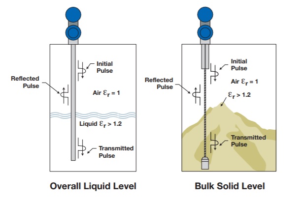
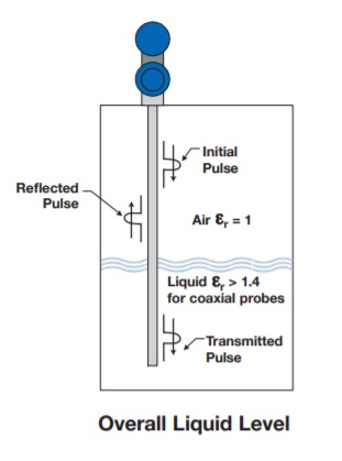
OVERALL LEVEL
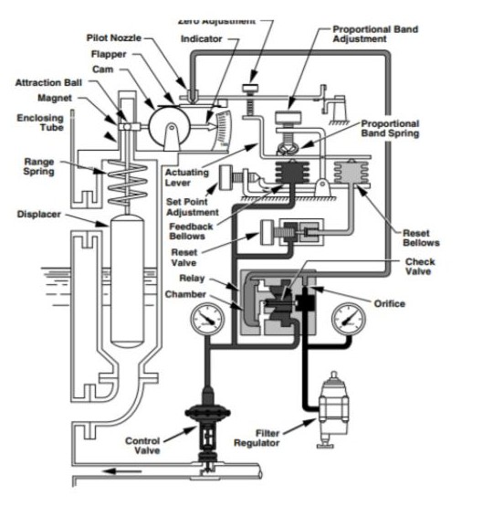
The Eclipse Model 705 Guided Wave Radar is based upon the technology of TDR (Time Domain Reflectometry). TDR utilizes pulses of electromagnetic energy transmitted down a wave guide (probe). When a pulse reaches a liquid surface that has a higher dielectric constant than the air (εr of 1) in which it is traveling,the pulse is reflected. The transit time of the pulse is then measured via ultra speed timing circuitry that provides an accurate measure of the liquid level.
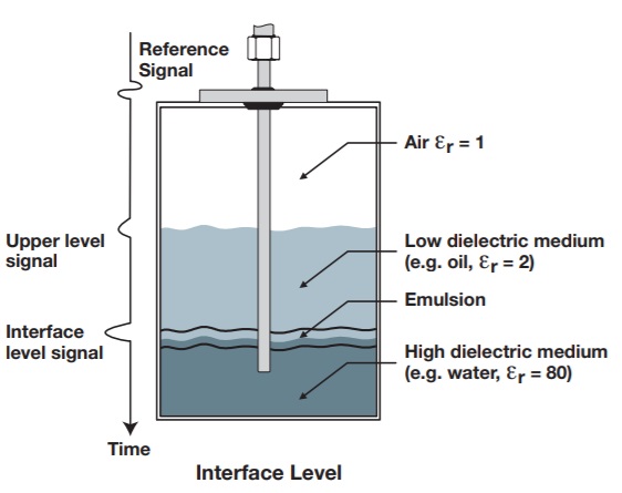
INTERFACE LEVEL
The Eclipse Model 705 is capable of measuring both an upper liquid level and an interface liquid level. Even after the pulse is reflected from the upper surface, some of the energy continues down the GWR probe through the upper liquid. The pulse is again reflected when it reaches the higher dielectric lower liquid. It is required that the upper liquid has a dielectric constant between 1.4 and 5,and the lower liquid has a dielectric constant greater than 15. A typical application would be oil over water, with the upper layer of oil being non-conductive (εr ≈ 2.0),and the lower layer of water being very conductive (εr ≈ 80). The thickness of the upper layer must be > 2″(50 mm). The maximum upper layer is limited to the length of the GWR probe, which is available in lengths up to 40 feet (12 meters).
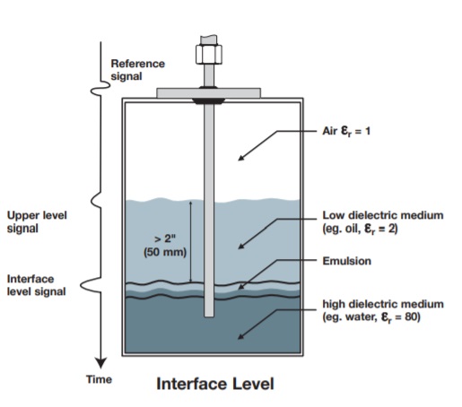
EMULSION LAYERS
As emulsion (rag) layers can decrease the strength of the reflected signal, the ECLIPSE Model 705 is recommended for applications that have clean, distinct layers. The ECLIPSE Model 705 will tend to detect the top of the emulsion layer. Contact the factory for application assistance regarding emulsion layers.
Features of Eclipse Model 705 for industrial applications
- “TRUE LEVEL” measurement—not affected by media characteristics (e.g., dielectrics, pressure, density, pH, viscosity, etc.)
- Two-wire, 24 VDC loop-powered transmitter for level, interface, or volume.
- 20-point custom strapping table for volumetric output.
- 360° rotatable housing can be dismantled without depressurizing the vessel.
- Two-line, 8-character LCD and 3-button keypad.
- Probe designs: up to +800 °F / 6250 psi (+430 °C / 430 bar).
- Saturated steam applications up to 2250 psi @+650 °F (155 bar @ +345 °C).
- Cryogenic applications down to -320 °F (-196 °C).
- Integral or remote electronics (up to 12 feet (3.6 m)).
- Certified for use in SIL 2/SIL 3 Loops (full FMEDA report available).
Applications of Eclipse Model 705 for industrial applications
MEDIA : Liquids or slurries; hydrocarbons to water-based media (dielectric 1.4 – 100).
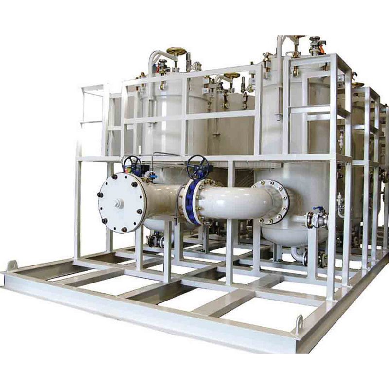
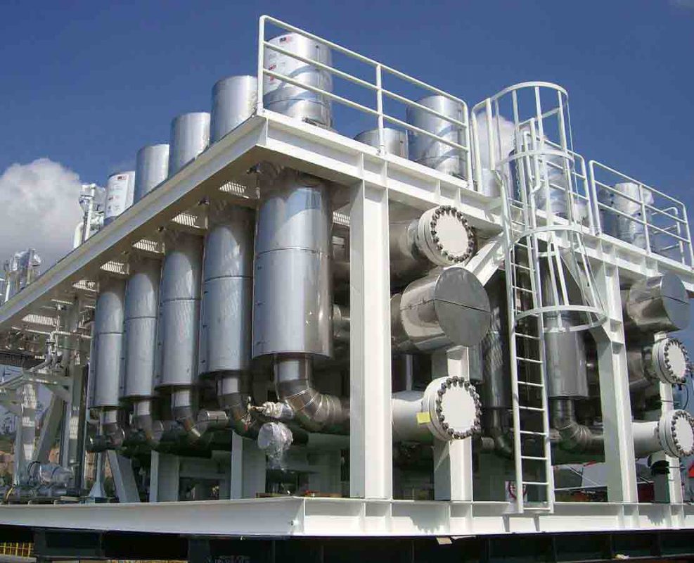
VESSELS : Most process or storage vessels up to rated probe temperature and pressure.
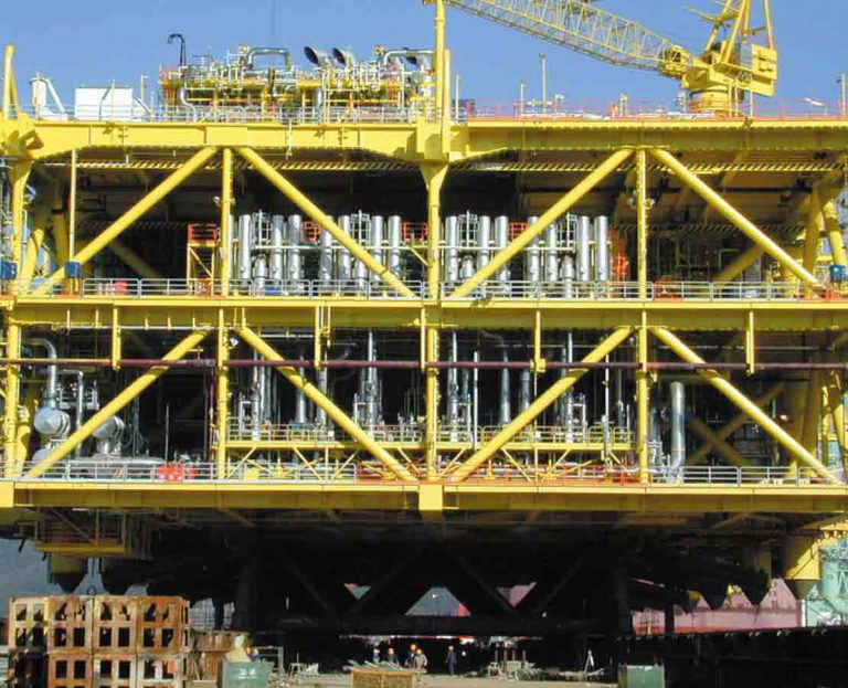
CONDITIONS : All level measurement and control applications including process conditions exhibiting visible vapors, foam, surface agitation, bubbling or boiling, high fill/empty rates, low level and varying dielectric media or specific gravity.
https://www.gmsthailand.com/product/eclipse-model-705-industrial/
The Enhanced Eclipse Model 705 Transmitter is a looppowered, 24 VDC liquid-level transmitter based on the revolutionary of technology on Guided Wave Radar (GWR).
Encompassing a number of significant engineering accomplishments, Eclipse Model 705 is designed to provide measurement performance well beyond that of many traditional technologies, as well as “through-air” radar.
About Eclipse Model 705, the innovative enclosure is a first in the industry, orienting dual compartments (wiring and electronics) in the same plane, and angled to maximize ease of wiring, configuration, and data display. One universal transmitter can be used with all probe types and offers enhanced reliability for use in SIL 2/SIL 3 hardware systems. ECLIPSE supports the FDT/DTM standard and, with the PACTware™ Frame Program, allows for additional configuration and trending flexibility
Technology of Eclipse Model 705 for industrial applications
OVERALL LEVEL
The Eclipse Model 705 Guided Wave Radar is based upon the technology of TDR (Time Domain Reflectometry). TDR utilizes pulses of electromagnetic energy transmitted down a wave guide (probe). When a pulse reaches a liquid surface that has a higher dielectric constant than the air (εr of 1) in which it is traveling,the pulse is reflected. The transit time of the pulse is then measured via ultra speed timing circuitry that provides an accurate measure of the liquid level.
INTERFACE LEVEL
The Eclipse Model 705 is capable of measuring both an upper liquid level and an interface liquid level. Even after the pulse is reflected from the upper surface, some of the energy continues down the GWR probe through the upper liquid. The pulse is again reflected when it reaches the higher dielectric lower liquid. It is required that the upper liquid has a dielectric constant between 1.4 and 5,and the lower liquid has a dielectric constant greater than 15. A typical application would be oil over water, with the upper layer of oil being non-conductive (εr ≈ 2.0),and the lower layer of water being very conductive (εr ≈ 80). The thickness of the upper layer must be > 2″(50 mm). The maximum upper layer is limited to the length of the GWR probe, which is available in lengths up to 40 feet (12 meters).
EMULSION LAYERS
As emulsion (rag) layers can decrease the strength of the reflected signal, the ECLIPSE Model 705 is recommended for applications that have clean, distinct layers. The ECLIPSE Model 705 will tend to detect the top of the emulsion layer. Contact the factory for application assistance regarding emulsion layers.
Features of Eclipse Model 705 for industrial applications
- “TRUE LEVEL” measurement—not affected by media characteristics (e.g., dielectrics, pressure, density, pH, viscosity, etc.)
- Two-wire, 24 VDC loop-powered transmitter for level, interface, or volume.
- 20-point custom strapping table for volumetric output.
- 360° rotatable housing can be dismantled without depressurizing the vessel.
- Two-line, 8-character LCD and 3-button keypad.
- Probe designs: up to +800 °F / 6250 psi (+430 °C / 430 bar).
- Saturated steam applications up to 2250 psi @+650 °F (155 bar @ +345 °C).
- Cryogenic applications down to -320 °F (-196 °C).
- Integral or remote electronics (up to 12 feet (3.6 m)).
- Certified for use in SIL 2/SIL 3 Loops (full FMEDA report available).
Applications of Eclipse Model 705 for industrial applications
MEDIA : Liquids or slurries; hydrocarbons to water-based media (dielectric 1.4 – 100).
VESSELS : Most process or storage vessels up to rated probe temperature and pressure.
CONDITIONS : All level measurement and control applications including process conditions exhibiting visible vapors, foam, surface agitation, bubbling or boiling, high fill/empty rates, low level and varying dielectric media or specific gravity.
https://www.gmsthailand.com/product/eclipse-model-705-industrial/